Note : At Present in Single Cylinder this instruction is up to 10/1 HP and in Twin Cylinder up to 16/2 HP. More details will be uploaded very soon. More or less of the information are same.
Note : At Present in Single Cylinder this instruction is up to 10/1 HP and in Twin Cylinder up to 16/2 HP. More details will be uploaded very soon. More or less of the information are same.
Foundations :
Our standard foundation drawings give the dimensions of suitable concrete beds. These dimensions are the minimum for a good solid subsoil and modification will have to be made where the subsoil is soft, water logged, or otherwise of a special character.
Set the engine as level as possible, packing under the engine feet with thin metal strips, placed as close as possible to the holding down bolts.
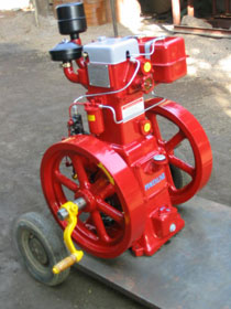
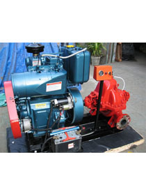
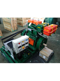
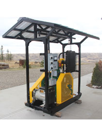
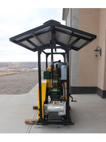
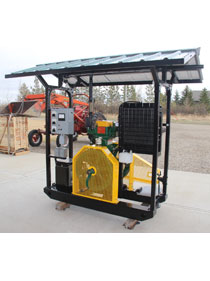
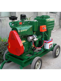
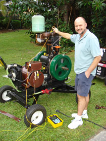
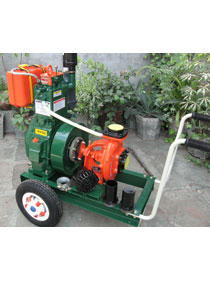
Portable Models :
Place portable models in as level a position as possible.
Belt Drive :
Driving belts must be run as close up to the flywheel as possible to avoid undue strain on the bearings and crankshaft. Where “fast” and “loose” pulleys are used, drive the “fast” pulley from the side nearest the flywheel.
Through Cooling :
The cooling of an engine by passing water through it to waste, with or without the use of a small tank, is totally unsuitable and must not be used under any circumstances.
Exhaust Pipes :
If a longer exhaust pipe than standard must be fitted, this should at no point slope upward from the engine, unless a suitable moisture trap is fitted at the lowest art of the pipe. This is to prevent moisture, caused by condensation, draining back into the cylinder and causing damage.
If more than 10 feet of pipe is used, the bore of the pipe must be increased.
Pipe sizes :
Up to 10 feet – 2 in. (50.8 mm.) bore
10 feet to 20 feet – 2½ in. (63.5 mm.) bore
over 20 feet – 3 in. (76.2 mm.) bore
To facilitate cleaning the exhaust Pipe during overhaul, it meet be erected in easily detached sections of about 4 feet in length and not concreted in at any Point.
Specification :
The fuel must be a DISTILLATE and not a residual oil or a blood thereof. It most conform with British Standard Specification
CLEAN FUEL IS OF THE UTMOST IMPORTANCE IN ENSURING RELIABLE AND EFFICIENT PERFORMANCE
Feel Service Tank :
An engine mounted fuel tank is supplied as standard; as an site, native, a fuel service tank can be supplied which should be mounted not less than 2 ft. 6 ins. (0.76 meters) and not more than 6 ft (1.8 meters) above the crankshaft and as close to the engine as possible.
This latter type is fitted with a loping bottom to assist in draining off sludge by means f a drain plug. During overhauls examine the tank closely and clean out if necessary.
Clients providing their own fuel tanks should arrange for the fuel outlet to be 2 in. above the bottom of the tank and that drainage arrangements we provided at the lowest point.
Always fill fuel rocks through a fine strainer, preferably at the end of a run. If any sediment is stirred up during the process, this has time to settle before the engine is used again.
If cam; am used, avoid tipping out the last few drops.
Funnels am very difficult to keep clean in dusty conditions. Wash them before and after use and wrap up when not required, or fill service tank direct from a small mouthed screw capped can such as a 2 gallon petrol can.
Tanks and piping should NOT be galvanized.
Before finally connecting up, blow out all fuel pipes to remove scale loosened during bending and fitting.
Specification :
The engine must be ran on good quality diesel engine heavy duty detergent lubricating oil.
The lubricating oils most meet specifications IS 496 Straight mineral oils am not suitable, neither are oils of less detergency than specified.
The use of good quality lubricants will give longer periods between overhauls and extend engine life.
Mixing of Oils :
If an engine has been on on straight mineral oil for more than 250 hours since completely overhauled (or since new) before it is changed to Heavy Duty (Detergent) Lubricants, the deposits formed by the straight oils may be dislodged by the letter and choke the oilways and filters. For this reason it is necessary to flush the engine thoroughly with Heavy Duty (Detergent) oil and change the oil after 150 hours and then resume normal changes every 250 hours. The filters must receive frequent attention during this initial period.
Sometimes Heavy Duty (Detergent) oils increase the oil consumption, in which case a heavier grade may be used.
DO NOT MIX TWO DIFFERENT BRANDS OF OIL. THOROUGHLY DRAIN OFF OIL OF ONE BRAND BEFORE CHANGING TO ANOTHER LUBRICATING OIL. ADDITIVES ARE NOT CONSIDERED NECESSARY AND SOME CAN HARM THE ENGINE.
 Lubricating Oil System 6/1 and 8/1
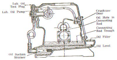 Lubricating Oil System 12/2 and 16/2
Lubricating Oil System :
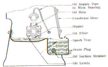
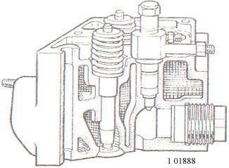
Lubrication is by a plunger type pump operated by a cam on the camshaft. The pump feeds a generous supply of oil to the main bearings and to the trough into which the dipper of the connecting rod big end dips. The big end bearings are lubricated from below by a hollow dipper in the 12/2 & 16/2 engines, and by oil holes from above in the single cylinder engines. The piston, cylinder and other working parts are lubricated by splash.
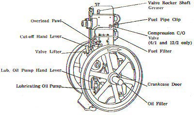
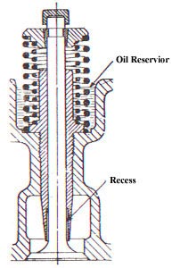
The lubricating oil pump of the single cylinder engines, mounted the end of the crankcase below the fuel pump is fitted with a hand priming lever. The two cylinder engine is primed from inside by reaching through the crankcase and working the oil pump plunger with the thumb until the oil is seen to flow down over the main bearings. The plug on the top of the pump fitting may be slackened if necessary to check that the pump is working. An oil pressure indicator gauge and tap can be supplied if specialty ordered. The valve stems are lubricated rated from small oil reservoirs in the cylinder head, and the rocker shaft is provided with its own greaser.
Near the valve tappets is a brass plug marked “OIL”. This is for applying oil to the camshaft bearing if the engine has been standing idle for a long time. Tappet heads and push rod heads are cupped to enable them to hold their own supply of oil for a reasonable time.
Before Starting Engine for the First Time of After Overhaul :
Lubricating Off Sump capacities :
6/1 and 8/1 … … … … 4.5 pints (2.6 liters)
1212 add 16/2 … … … … 10 pint (5.7 liters)
To Start Engine by Hand :
To Stop Engine :
Speed and Load Regulation :
A slight adjustment of speed may be made. To increase speed, turn the knurled adjusting nut in a clockwise direction, increasing the tension of the spring. To reduce the speed, turn the knurled nut in the opposite direction.
THE SPEED MARKED ON THE ENGINE MUST NOT BE INCREASED BY MORE THAN 2½%.
Essential for Easy Starting :
Essential for Easy Starting :
This my be caused by :
Carbon Deposit :
Excessive deposit may be due to :
Smoky Exhaust :
The exhaust gas should be clear at full load. If it is not, steps should be taken to clear it. Black smoke is due to incomplete combustion of fuel caused by :
Blue smoke, when faint, is generally the result of light load on over cooling.
Heavy blue smoke is caused by lubricating oil passing the piston rings because of either piston rings carboned in grooves or a worn cylinder.
Engine Stop :
This may be due to :
Loss of Power :
This may be due to :
Failure to obtain Normal Speed :
Cooling :
Occasionally examine flexible hose to see that it is clear. There is a danger of swelling inside, so obstructing the flow of water, and a good test is to compress the hose, which should give and not feel hard and solid.
In districts where the water is impure, the water jacket around the cylinder and in the cylinder head should be freed from any deposit.
To remove hard deposits in cylinder water jacket fill with a solution of washing soda in the proportion of 1¼ lbs. of soda to 1 gallon of boiling water. Then wash the jacket out with fresh water.
When Engine is in regular use :
100 Hours:
250 Hours:
500 Hours:
1000 Hours:
A reasonable amount of time spent in checking over the details as described in the foregoing is the user’s best insurance against loss of valuable time and costly repairs.
Changing Oil :
Change lubricating oil after every 250 hours running.
Drain sump when engine is warm through drain plug to be found on 6/1 and 8/1 engines below the oil filter, and on 12/2 and 16/2 engines in the oil suction pipe below.
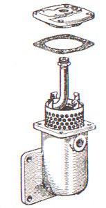
Remove crankcase door, splash plate (6/1 and 8/1) and lubricating oil strainer.
Wipe down inside of crankcase, including trough, as clean as possible.
If paraffin is used to clean out sludge, crankcase must be wiped dry before recharging with fresh oil.
Clean and replace oil strainer.
The fuel filter is an essential part of a diesel engine. It must not be removed from the engine or used without a filter element.
Renew the filter element every 1000 hours – more frequently if the fuel is known to be dirty for any reason. When changing the element clean the inside of the filter bowl.
After carefully re-assembling the filter, the fuel should be turned on and all air vented from the system by slackening the two bleed screw on top of the filter body, and the single bleed screw in the outlet banjo. After all air has been displaced tighten the vent screws securely.
Felt Air Filter (When supplied) :
Air filter is suitable for average operating conditions, but where very dusty conditions prevail an “oil bath” filter should be fitted.
It is important that the air filter is cleaned regularly so that the passage of air to the engine does not become partially or wholly blocked. The time interval between cleanings will vary with the amount of dust in the air, but it is recommended that this operation should be performed once a month under the cleanest of conditions.
Remove felt from cleaner and shake vigorously, then beat dust and grit out of the felt.
If the felt is damp and oily it will be necessary to wash it in paraffin and the thoroughly dry before replacing in the cleaner. Fuel oil is NOT recommended for washing the felt as it will not readily evaporate and petrol vapor may cause detonation.
Oil Bath Type Air Filter (When Supplied) :
Mount the filter in horizontal position and maintain the correct oil level as marked on the filter body. If the level is ¼ in. Too high the engine will inhale the cleaning oil, which will cause excessive carbon deposits on the valves, pistons, etc. If too little oil is used the cleaning action will not be efficient. Check the oil level weekly, and if necessary and fresh oil. Lubricating oil as used for the engine may be employed. Change the oil and clean completely every 500 hours running, or more frequently if there is any sign of the oil becoming impregnated with sand of dirt. To clean, remove from engine and dismantle. Wash in paraffin and allow to dry. Examine cork and felt washers during dismantling and change if necessary.
Air tight joints, including those between the filter and the engine are essential for efficient air cleaning.
Vacuum Breather :
The purpose of the vacuum breather on the crankcase door is to maintain a partial vacuum in the crankcase so that the lubricating oil will not work out through the bearings and joints.
If the thin metal disc should become stuck with paint or grime, remove and scrape clean on the flat surface, care being taken not to kink or distort it. Do not mislay the small distance piece which supports the cover.
To Remove Compression Change-Over Valve (6/1 and 12/2 only) Option Extra :
This is device to give a high compression for starting, and lower compression for normal running.
The Valve screwed “IN” give high compression and “OUT” gives low compression.
DO NOT run under heavy load with high compression.
For long runs at 1/3 load or less, use high compression.
Always see the valve is either Full in or Fully Out.
Keep the screw thread clean and bright.
Drive a hard wooden Plug into the ¼ in. dia. hole in the center to prevent air leakage and then replace the outer portions just removed with the hand wheel in the “Out” position, and with the outer combustion chamber nut screwed into the head three or four turns which will be sufficient to prevent the inner combustion chamber from being ejected too violently when subjected to the force of compression.
Stubborn cases will have to be treated by drilling and tapping with a fine 3/8 in. thread and drawing out with a screw.
To Remove Cylinder Head :
Next proceed as for starting. With valve lifter engaged, turn the starting handle quickly to get up a good speed and then smartly disengage valve lifter, when the compression in the cylinder should cause the loosening of the joint between cylinder head and cylinder block.
To Remove Valve Guides :
To Replace Cylinder Head :
Note: In the twin cylinder engine the cylinder heads are so arranged that the two inlet valves come together on the inside, the parts being connected by a common inlet manifold. The cylinder heads, therefore, most be replaced in their original positions.
Note: Each cylinder head gasket must be replaced on its own cylinder If these have been changed then the head clearance must be checked as below.
To Check Cylinder Head Clearance :
Place two small pieces of lead on top of piston, above the line of the gudgeon pin and not beneath the valves of transfer port. Tighten down cylinder head and turn piston slowly past T.D.C. Remove cylinder head and measure thickness of lead; this should fall between 0.045 in. (1.14 mm.) and 0.050 in. (1.27 mm.) for types 6/1 and 12/2 and between 0.0075 in. (1.9 mm.) and 0.080 in (2.03 mm.) for the 8/1 and 16/2 engines. The clearance may be adjusted by the use of paper joints, placed between the cylinder block and the crankcase.
If the clearance is much too large it my be due to worn bearings or a bent connecting rod.
To Remove Piston :
Note : which way the dipper faces and the manner in which the big end is marked, so that it can be assembled i the same way.
To Remove Piston Ring :
First work them loose, then stand the piston on a flat surface, and insert thin strips of metal between the top ring and the piston at four different places. Ease the ring off over the strips of metal, and repeat the process for the other rings. Piston rings are springy hot will break if roughly handled.
To Replace Piston Rings :
To Reassemble :
Connecting Rod Big End Bearing :
These are steel back white metalled shells in the bottom half and lead bronze in the top half and mast not be scraped or touched up in any way. The running clearance with the crankpin should not exceed 0.003 in. (0.076 mm.).
When assembling the bearings on the connecting rod it is most important that the backs are scrupulously clean and that there is interference between the bearing and the bore of the connecting rod. This interference, or nip, is measured by placing the bearing in the connecting rod, tightening both bolts to the normal extent, then slackening one bolt only and measuring the corresponding gap in the rod at the parting line. This gap should be between 0.004 in. (0.102 mm.) and 0.006 in. (0.152 mm.).
Ensure the dipper is secure before replacing the connecting rod cap; it is screwed in place and 4 dots punched into the circumference prevent turning. Place a cork over the end of the dipper whenever working in the crankcase to avoid injury to the hands.
Tightening torque for big end nuts is 55 lb. ft. (7.6 kg. m.)
Main Bearings :
These are of the bush type and need no attention as long as they are properly lubricated. The bush is located in the housing by a locating screw through the top of the housing, to ensure that the oil holes register correctly.
Valves Adjustment :
Valve Tappet clearance should he set to
6/1 and 12/2 … Inlet, 0.017 in. (0.43 mm.); Exhaust, 0.032 in. (0.82 mm.).
8/1 and 16/2 … Inlet, 0.008 in. (0.20 mm.); Exhaust, 0.008 in. (0.20 mm.).
To do this, slack. off the lockout on top of the valve rocker, turn the adjusting screw by means of a screwdriver until the correct clearance is obtained between the valve and rocker and then tighten the lockout. During this operation the valve tappet most be in its lowest position, and the rocker pressed firmly down on the push rod.
To Remove Valve :
To Replace Valves :
Replace components in the reverse order and check valve clearance under the face of the cylinder head.
Position of Valve Hands :
Inlet and exhaust valve heads must not be less, than 0.055″ (1.39 mm.) and not more than 0.100″ (2.54 mm.) under face of cylinder head to prevent valves from touching piston when using the valve lifter.
Decarbonising
ENGINE SHOULD NOT BE RUN MORE THAN 1,000 HOURS WITHOUT DECARBONISING.
ALL PARTS must be scraped clean of deposits of carbon and washed in paraffin before reassembly.
Special care must be take, with regard to :
Regrind valve seats if not in perfect condition. This applies also to the compression change-over value (6/1 and 12/2 only.)
Clean out all exhaust piping, expansion chambers, silencers, etc. Every part must be scrupulously clean before being placed in position.
To Remove flywheel :
In case of difficulty the crankshaft can be withdrawn from either end of the engine with one flywheel still attached.
To Remove Camshaft :
Assemble in reverse order, replacing tappets first. These may be held in position with thick grease.
Note :The idler pinion spindle has an oil groove which MUST be fitted at the top for lubrication of the bearing.
To Time Camshaft :
When reassembling, the timing marks “I” and “O” must be matched as illustrated.
Note :Care must be take, to ensure crank arm, does not hit idler pinion spindle when turning the crankshaft to match the timing marks.
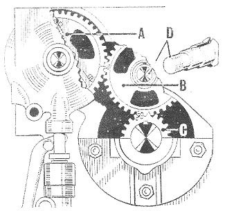
A – Camshaft Gearwheel
B – Idler Gear
C – Crankshaft Pinion
D – Idler Gear Spindle
Camshaft Timing
To Remove Camshaft :
On single cylinder engine the crankshaft may, if desired, be removed without first drawing piston and connecting rod.
On twin cylinder engines the cylinder blocks, connecting rods and center main bearing bolts have to be removed before removing the crankshaft.
Fad Pump :
To Tim Injection
At this position the mark on the flywheel rim which indicates injection should be immediately opposite the center line of the cylinder block.
The timing mark is 20º before TDC or 41/8 (104.77 mm.) on the rim of a 235/8″ (60 cms.) dia. flywheel and 43/8″ (111.125 mm.) on the rim of a 25″ (63.5 cm.) dia. flywheel for engines except 16/2 which is 26º before TDC or 5¼” (133.35 mm.) on rim of 235/8″ (60 cms.) diam. flywheel and 8/1 which is 19º before TDC.
To Refit Crankshaft :
On single cylinder engine the crankshaft may, if desired, be removed without first drawing piston and connecting rod.
The crankshaft end play should be adjusted to 0.005″/0.010″ (0.127 mm./0.254 mm.) when fitting the flywheels.
Lubricating Oil Pump :
This requires very little attention, but bell valves, scats and plunger must be renewed when worn, for efficient operation.
12/2 and 16/2 Engines. It may be necessary to prime the pump after a major overhaul or renewal of lubricating oil. Unscrew pressure gauge or plug and pour oil into the pump discharge; replace pressure gauge or plug.
To Prime Feel System :
Prime the fuel system by removing ALL air :
Fuel Pump Fault Location :
| FAULT | PROBABLE CAUSE | SUGGESTED REMEDY |
| Pump does not deliver fuel. |
|
Partly unscrew vent plug and turn engine until fuel flows freely, without any air bubbles.Remove and examine valve face and guide, as well as seating face. If either is damaged, the pair should be replaced. |
| The pump does not deliver fuel uniformly. |
|
Increase of “head”.
Proceed as at 3.
Replace. Fit new pair (i.e. new valve and seating complete). |
| Pump delivers insufficient fuel. |
|
Fit new pair (i.e. valve and seating).Clean joint faces and tighten down. |
To Adjust Fuel Pump Linkage (12/2 & 16/2 Engine) :
Fuel pumps are calibrated as indicated by two center punch marks on the fuel pump rack. When these are equally disposed about the rack facings on the pump body, the pump is delivering fuel corresponding to full power The procedure for adjustment is as follows :
To Prime Feel System :
Examine the nozzle if trouble is suspected and clean if necessary. The use of absolutely clean fuel ensures the maximum of time with trouble free injectors. The injectors should be set to 90 atmosphere for 6/1, 8/1 and 12/2 engines and 150 atmospheres for 16/2 engines.
A faulty nozzle may result in one or more of the following :
To test a nozzle, remove from cylinder head and reconnect to fuel injection pipe with nozzle exposed. Tom the engine until, the nozzle sprays into the air away from the operator (the spray will easily penetrate the skin of the hands) when it will be seen if the spray is streaky or dribbling; a perfect spray is in the form of a fine mist.
The nozzle must only be cleaned with the necessary special tools and by a qualified service engineer.
Remove nozzle and valve, replace with a new pair and return the defective unit to a service depot for attention.
IMPORTANT :
Apart from the attention giver. to the fuel pump delivery valve and the changing of defective injector nozzles and valves, ALL other work on the fuel injection system must be carried out by suitably equipped service depots.